|
|
|
|
مواقع
مفضله
Molded
case circuit breakers are the circuit breakers which Their
current carrying parts, mechanisms and trip devices are completely contained
within a molded case of insulating material. MCCBs are available in
various frame sizes with various interrupting ratings for each frame size. Molded
case circuit breakers are designed to provide circuit protection for low voltage
distribution systems. They protect connected devices
against overloads and/or short circuits. Molded
case circuit breakers are available with special features making them suitable
for the protection of motor circuits when used in conjunction with a separate
overload protection device. In these applications, they are often referred to as
motor circuit protectors (MCPs).
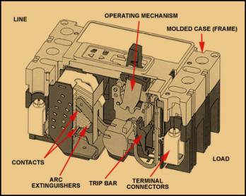
Figure
1. Five Main Components of an MCCB
The
function of the frame is to provide an insulated
housing to mount all of the circuit breaker components. The frame is often of a
glass-polyester material or thermoset composite resin that combines ruggedness
and high dielectric strength in a compact design. The frame is also known as a
molded case. A
frame designation is assigned for each different type and size of molded case. This
designation is used to describe the breaker's characteristics such as maximum
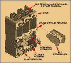
voltage and current ratings. Figure
2. Motor Circuit Protector Components
●How
It Operates Motor
circuit protectors disconnect the motor load from an electrical supply under
three conditions. They are:
Its
design provides an increased air gap between the stationary and moveable
contacts when in the tripped position. This air gap
results in greater arc extinguishing during contact opening and provides higher
interrupt ratings.
Motor
circuit protectors can be used in combination starter units within a motor
control center. They allow for protection
against both low and high level fault currents. They can also
be applied in standalone combination starters.
A
shunt trip provides remote controlled
tripping of a molded case circuit breaker. A
solenoid coil is remotely energized
using a pilot device, such as a pushbutton. That moves the plunger to activate
the trip bar of the breaker. At the same time, a cutoff switch operates which
disconnects power to the solenoid so the coil doesn't burn out. Often, pigtail
leads are supplied for connecting the shunt trip to either an AC or DC control
power source.
Auxiliary
switch Providing
circuit breaker main contact status, an auxiliary switch is mounted in the
breaker. In this diagram, the contacts are
shown as "A" and "B". An "A" contact is open when
the breaker is open or tripped. A "B" contact is closed when the
breaker is open or tripped. The contacts are rated 120V . Figure
3. Auxiliary Switch Contacts If
you wanted to give a visual indication that a circuit is energized, you could
mount an indicating light on the panel. Using an auxiliary switch with an
"A" contact would allow the light to be illuminated whenever the
breaker is closed. When the breaker trips, the light goes off, letting you know
the breaker has tripped or been opened. Auxiliary
switches can be used for circuit interlocking purposes. The
NEC requires that motor control circuits be disconnected from all sources of
supply when the disconnect means is in the open position. For starters with
common control, one circuit breaker would disconnect the voltage for both the
power circuit and the control circuit. If the control circuit has a separate
power supply, the circuit breaker would not disconnect that supply source. You
could use separate disconnect means, or simply use an auxiliary switch in the
breaker. When the breaker is open, the auxiliary opens the control circuit,
disconnecting it from its supply source. Figure
4. Auxiliary Contacts Disconnect Separate Control Power Source Alarm
switches Alarm
switches differ from auxiliary switches in that they function only when the
breaker trips automatically.
The normally open contact of the switch closes when the breaker trips due to a
short circuit, an overload condition, or when operated by a shunt trip. An
indicating light, or a bell can be placed in the circuit to provide indication
that the circuit has tripped. When the breaker is reset, the alarm switch is
reset. A manual opening of the circuit breaker does not affect the alarm switch
contact.
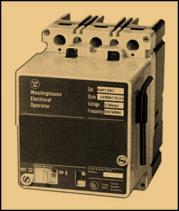
Handle
operating devices provide indirect electrical or manual operation of the circuit
breaker handle. Electrical
operators provide complete remote control of a molded case circuit breaker by
means of a pushbutton. When energized from
a remote location, the operator mechanism moves the circuit breaker handle to
either the ON or OFF position. Shunt trips and undervoltage release mechanisms
can only be used to trip the breaker. Electrical operators deliver a positive
switching action. In case of a power failure, means are provided for manual
operation. They come in a variety of designs and, depending on the circuit
breaker type, are mounted in different ways. The
newer designs are front mounted on the breaker cover and fit within the trim
line of the circuit breaker. For smaller
frame breakers, a solenoid is used. On larger frame sizes, a motor is used to
provide the increased operational force required to move the breaker handle. Figure
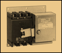
5. Front Mounted Electrical Operator (Solenoid Type) Some
designs are side mounted and use an extended arm to move the circuit breaker
handle. These older motor driven operators
are not usually suitable for generator synchronizing because of the time it
takes for operation. Figure
6 Side Mounted Electrical Operator (Motor Type) modern
electrical operator designs, whether solenoid or motor driven, are capable of
performing a closing operation in five cycles or less. This makes them very
suitable for generator synchronizing applications.
|
|
تصميم المهندس : محمد صبري محمود فهيم إستعداد تام لتصميم المواقع إستعداد تام للعمل داخل أو خارج مصر E-Mail: Mohamedmsm@Masrawy.com |
 What
What